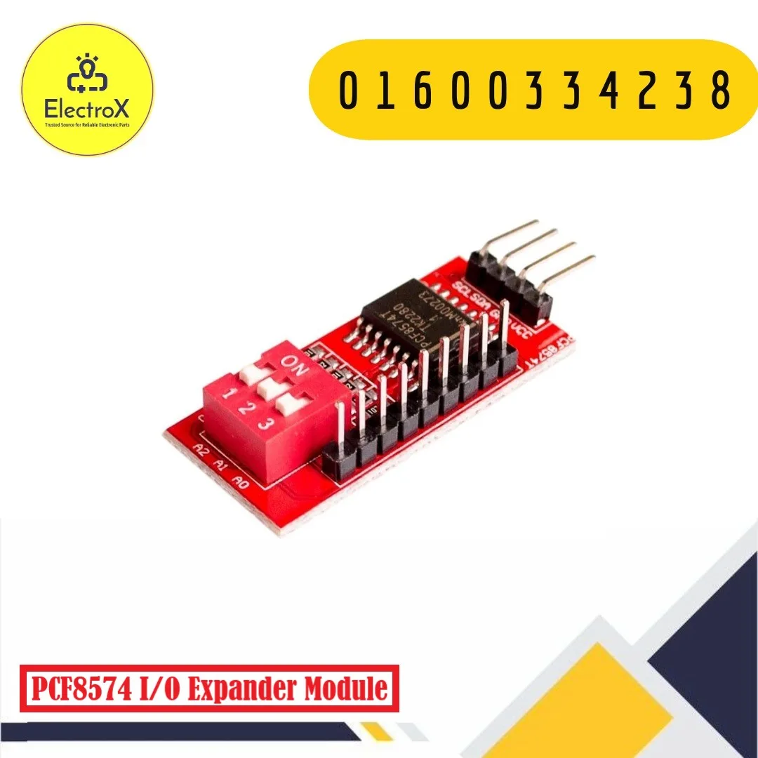
PCF8574 I/O Expander Module Board I2C Interface
৳ 150
- Main IC: PCF8574
- Communication Interface: I2C
- Digital I/O: 8 I/O pins (P0–P7)
- Operating Voltage: 2.5–6V
- Address Selection: A0, A1, and A2
1 in stock
PCF8574 I/O Expander Module Board Price in Bangladesh
The PCF8574 I/O Expander Module Board is a practical solution for electronics projects that require more digital input/output pins than a microcontroller provides. Using the I2C communication interface, the module allows a controller to communicate with eight additional digital I/O lines through just two signal wires: SDA for serial data and SCL for the serial clock.
Microcontrollers such as Arduino boards and ESP32 development boards provide a limited number of GPIO pins. As a project grows, these pins may be needed for sensors, displays, buttons, indicator LEDs, and other peripherals. Adding another controller can increase complexity, but an I/O expander provides another option by extending the available digital interface through the I2C bus.
At the centre of this module is the PCF8574 integrated circuit, an 8-bit I/O expander developed for I2C-based systems. Its eight ports, labelled P0 through P7, can be used for compatible digital input and output tasks. The device uses quasi-bidirectional I/O rather than a conventional direction register, so the software must manage each pin according to the chip’s operating method.
The PCF8574 is particularly useful for projects involving push buttons, switches, LEDs, simple digital control signals, and keypad interfaces. It is also commonly used on I2C LCD adapter boards, where it helps control an LCD using fewer microcontroller connections.
The module communicates with the host controller using an I2C address. On boards that expose the A0, A1, and A2 address pins or jumpers, these settings allow the address to be changed so that multiple compatible devices can share the same I2C bus, provided their addresses do not conflict.
Depending on the specific breakout-board design, the module may include header pins, address jumpers, pull-up resistors, or additional connectors. Check the supplied board’s layout and labels before connecting it to your controller.
What Is an I/O Expander?
An I/O expander is an integrated circuit or module that increases the number of input/output connections available to a microcontroller. Instead of using a separate controller pin for every signal, the host communicates with the expander through a shared serial interface.
The PCF8574 uses I2C, a two-wire communication protocol. The SDA line carries data, while SCL provides the clock signal. Devices on the same bus communicate using their assigned addresses.
This approach reduces wiring and conserves GPIO pins. It is especially useful when several digital devices must be connected to one microcontroller.
The PCF8574 provides eight quasi-bidirectional digital ports. These ports can be used as inputs or outputs through software-controlled port data. However, the chip is not a complete replacement for every microcontroller GPIO feature. Its ports do not provide the same capabilities as analog inputs, PWM outputs, or high-current power outputs.
Key Features
1. Eight Additional Digital I/O Pins
The module provides eight digital ports, P0–P7, for supported input and output functions. These can be used to read button states, monitor switches, and control suitable digital devices.
2. I2C Two-Wire Communication
The PCF8574 communicates through SDA and SCL, allowing it to share the I2C bus with compatible sensors, displays, and other peripheral modules. This helps reduce the number of connections required between the controller and external devices.
3. Reduced GPIO Usage
Only two I2C signal lines are needed for communication, apart from power and ground. This helps preserve the controller’s remaining GPIO pins for other functions.
4. Address Configuration
The PCF8574 family provides three hardware address inputs. Compatible boards may expose these as pins or solder jumpers, allowing address selection for multiple devices on one bus.
5. Supports Digital Inputs
The quasi-bidirectional ports can be used to read digital inputs such as push buttons and switches when configured correctly in software. Suitable external circuitry may be required for some input applications.
6. Supports Digital Outputs
The ports can control compatible digital loads such as indicator LEDs through appropriate current-limiting components. They are not designed to power high-current motors, relays, or other demanding loads directly.
7. Useful for LCD and Keypad Projects
PCF8574 devices are widely used in I2C LCD adapter circuits and can also simplify digital keypad and switch interfacing.
8. Suitable for Embedded Development
The module can be incorporated into compatible Arduino, ESP32, Raspberry Pi, and other microcontroller projects. Voltage compatibility must be checked for the specific controller and board.
Technical Specifications
| Parameter | Specification |
|---|---|
| Product Name | PCF8574 I/O Expander Module Board |
| Main IC | PCF8574 / compatible family variant |
| Module Type | Digital I/O expansion board |
| Communication Protocol | I2C |
| Communication Pins | SDA, SCL |
| Number of I/O Ports | 8 |
| Port Labels | P0–P7 |
| I/O Architecture | Quasi-bidirectional |
| IC Operating Voltage | 2.5–6V |
| Common Module Supply | 3.3V or 5V, depending on board design |
| Hardware Address Inputs | A0, A1, A2 |
| PCF8574 7-Bit Address Range | 0x20–0x27 |
| PCF8574A 7-Bit Address Range | 0x38–0x3F |
| Interrupt Output | INT, active-low on supported versions |
| Compatible Platforms | Arduino, ESP32, Raspberry Pi and other compatible controllers |
| Typical Applications | GPIO expansion, buttons, LEDs, LCD interfaces and digital control |
Important specification note: PCF8574 and PCF8574A variants use different address ranges. The board’s exact chip variant and address-selection arrangement should be verified before publishing a default address. The chip itself supports 2.5–6V operation, but a breakout board’s pull-up resistors and wiring can affect safe use with 3.3V controllers.
Working Principle
The PCF8574 works as an intermediary between a microcontroller and eight digital I/O ports. The microcontroller sends data to the chip through the I2C bus, and the chip updates its port states according to the received information. It can also return the state of the ports when the controller requests a reading.
First, the module is connected to the controller’s power, ground, SDA, and SCL lines. The controller communicates with the device using its I2C address. Once the connection is established, software can write a byte to control the port states or read a byte to obtain input information.
Each bit in the byte corresponds to one of the eight ports. This allows the controller to manage several digital signals through a single data transfer. For example, a project can use some ports to read buttons and others to control LEDs, subject to the chip’s quasi-bidirectional behaviour and appropriate circuit design.
The PCF8574 does not use a conventional data-direction register. To use a port as an input, software generally writes a high value to that port and then reads its state. The pin can then be pulled low by an external circuit when the input is activated. The exact electrical arrangement should follow the manufacturer’s datasheet.
Address pins A0, A1, and A2 set the hardware address bits. This makes it possible to connect multiple devices of the same compatible family to a shared I2C bus, as long as each device has a unique address and the bus wiring is suitable.
The module is an I/O expander, not a power supply or a general-purpose analog converter. It is intended for digital interfacing rather than analog voltage measurement, precision PWM generation, or directly driving high-current equipment.
Applications
Arduino GPIO Expansion
Use the PCF8574 to increase the number of available digital I/O lines on compatible Arduino boards. It is useful when the project has more buttons, LEDs, or digital signals than the controller can conveniently accommodate.
ESP32 Projects
The module can extend the digital interface of an ESP32-based project. Ensure that the I2C bus pull-up voltage is compatible with the ESP32’s 3.3V logic.
Raspberry Pi Digital Interfacing
In compatible Raspberry Pi projects, the PCF8574 can provide extra digital ports through I2C. Check the board’s voltage and pull-up arrangement before connecting it to the Pi.
LCD Interface Projects
The PCF8574 is commonly used in I2C adapter boards for character LCDs. Similar functionality can be used in compatible display-interface designs to reduce the number of controller pins required.
Push-Button and Switch Inputs
The eight ports can be used to monitor buttons and switches through suitable digital input circuits and software.
LED Indicator Control
The module can control suitable LED indicator circuits when current-limiting resistors and the IC’s electrical limits are respected.
Keypad Interfacing
A compatible keypad interface can use the expander to read multiple digital switch states while saving microcontroller pins.
Home Automation Prototypes
It can support low-current digital control and status monitoring in prototype automation systems. Additional driver circuits are required for loads such as motors, solenoids, and many relay coils.
Embedded Systems Education
The module provides a practical way to learn about I2C communication, device addressing, port expansion, and digital input/output control.
Advantages
- Adds eight digital I/O ports through a compact module.
- Uses only two signal wires for I2C communication.
- Helps conserve microcontroller GPIO pins.
- Supports configurable hardware addressing on suitable boards.
- Can share an I2C bus with compatible peripherals.
- Useful for digital input and output experiments.
- Commonly supported by microcontroller libraries.
- Suitable for educational projects, prototyping, and embedded development.
Limitations
The PCF8574 provides digital I/O only. It does not provide analog input channels, hardware PWM generation, or high-current outputs comparable to dedicated driver circuits.
Its quasi-bidirectional ports require appropriate software handling, especially when reading inputs. Electrical current capabilities are limited, so the module should not be used to power motors, large LEDs, relay coils, or other high-current loads directly.
I2C communication depends on suitable pull-up resistors, compatible logic levels, correct wiring, and unique device addresses. Long wires or excessive bus capacitance can cause communication problems.
Finally, PCF8574 and PCF8574A devices have different I2C address ranges. Software must use the correct address for the installed chip and board configuration.
Installation and Usage Tips
- Connect VCC and GND according to the module’s voltage requirements.
- Connect SDA and SCL to the controller’s corresponding I2C pins.
- Verify the pull-up voltage before connecting the module to a 3.3V controller such as an ESP32 or Raspberry Pi.
- Check the PCF8574 or PCF8574A variant and set the correct I2C address.
- Use an I2C scanner or suitable software to confirm that the device responds at the expected address.
- Configure ports appropriately in software before using them as inputs or outputs.
- Use current-limiting resistors for LEDs and suitable driver circuits for higher-current loads.
- Keep wiring short and ensure a common ground between the controller and module.
- Consult the manufacturer’s datasheet for electrical limits and the correct operating method.
Why Choose the PCF8574 I/O Expander Module?
The PCF8574 I/O Expander Module is a practical option when a microcontroller project needs additional digital inputs and outputs without consuming a large number of GPIO pins. Its I2C interface simplifies wiring and allows compatible peripherals to share the same communication bus.
With eight digital ports and hardware address configuration on supported boards, it is useful for projects involving switches, LEDs, keypads, LCD interfaces, and embedded control systems.
For reliable operation, select a board compatible with your controller’s logic voltage and confirm the I2C address before integrating it into the project.
Why Buy from ElectroXBD?
ElectroXBD supplies electronic components, development modules, sensors, and accessories for students, hobbyists, makers, laboratories, and engineering projects in Bangladesh.
Whether you are developing an Arduino project, expanding an ESP32 interface, or building an embedded electronics prototype, ElectroXBD helps you source components for your project requirements.
Business Address: H#1/1, Opposite of RH Chhatrabash, Vodra-Talaimari Road, Rajshahi, Bangladesh.
Website: electroxbd.com
Contact / WhatsApp: 01600334238
Email: electroxbd@gmail.com
Frequently Asked Questions (FAQ)
1. What is a PCF8574 I/O Expander Module?
It is an I2C-based digital I/O expansion module that provides eight additional quasi-bidirectional digital ports for compatible microcontrollers.
2. How many I/O pins does the PCF8574 provide?
The PCF8574 provides eight digital I/O ports, labelled P0 through P7.
3. Which communication interface does this module use?
It uses I2C communication through the SDA data line and SCL clock line.
4. Can I use the PCF8574 with Arduino?
Yes. It can be used with compatible Arduino boards through the I2C interface and suitable software libraries.
5. Is the PCF8574 compatible with ESP32?
Yes, provided the module’s I2C signals and pull-up voltage are compatible with the ESP32’s 3.3V logic.
6. What is the operating voltage of the PCF8574?
The IC supports a supply voltage from 2.5V to 6V. The exact module’s supply requirements depend on its board design.
7. What is the default I2C address?
The address depends on the chip variant and address-pin configuration. PCF8574 devices use 7-bit addresses from 0x20 to 0x27, while PCF8574A devices use 0x38 to 0x3F.
8. Can I connect multiple PCF8574 modules to one I2C bus?
Yes. Multiple devices can share the bus if each has a unique address and the bus’s electrical requirements are met.
9. Can the module drive motors or relay coils directly?
No. The I/O pins have limited drive capability. Use a suitable transistor, MOSFET, motor driver, or relay driver circuit for higher-current loads.
10. Where can I buy a PCF8574 I/O Expander Module in Bangladesh?
You can buy the PCF8574 I/O Expander Module from ElectroXBD, a trusted electronics components supplier in Bangladesh. Visit electroxbd.com or contact 01600334238 for availability.
Common Questions:
Q: What is the price of PCF8574 I/O Expander Module Board I2C Interface in Bangladesh?
A: The latest price of PCF8574 I/O Expander Module Board I2C Interface in Bangladesh is 150 BDT.
Q: Where to buy PCF8574 I/O Expander Module Board I2C Interface in Bangladesh?
A: You can buy the PCF8574 I/O Expander Module Board I2C Interface at the best price from ElectroXBD in Bangladesh.
Only logged in customers who have purchased this product may leave a review.
FAQs
Related products
-
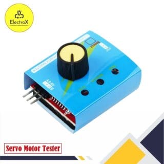
Servo Motor Tester Module
৳ 150Add to cart- Input Voltage: Servo Motor Tester perates on 4.8V to 6V DC.
- Testing Modes: Supports manual, neutral, and automatic sweep modes.
- Control Knob: Equipped with a rotary knob for manual testing.
- Output Interface: Includes three output connectors to test up to three servos simultaneously.
- Compact Design: Lightweight and portable for easy integration into various projects.
-
MP3 Lossless Decoder Module
Original price was: ৳ 300.৳ 250Current price is: ৳ 250.Add to cart- MP3 Lossless Decoder Audio Formats: Supports MP3, WAV, WMA, FLAC, APE.
- Output Interface: Stereo 3.5mm audio jack.
- Power Supply: 5V DC.
- Storage: MicroSD card, USB drive support.
- Control Interface: Buttons for play, pause, next, and previous.
-
HCW-M421 Timer Relay Switch for Incubator
Original price was: ৳ 300.৳ 220Current price is: ৳ 220.Add to cart- Timer Relay Operating Voltage: 5V, 12V, or 24V DC (varies by model).
- Timing Range: Adjustable from 0.1 seconds to 999 minutes.
- Load Capacity: Supports up to 10A at 250V AC or 30V DC.
- Modes: Multiple timing modes, including delay on, delay off, and cyclic timing.
- Display: LED display for easy time setting and monitoring.



Reviews
There are no reviews yet.